Single Axis Solar Tracker 555 ic
Make Single Axis Solar Tracker without Any Programming
Solar energy is the most popular eco-friendly energy resource nowadays. Number of people installing solar energy generation systems for general use is increasing day by day around the globe. Solar energy, which is the energy we receive from the Sun, is widely available and it is free as well. So why not utilise it for energy/ electricity production. People have already started making use of solar energy to produce electricity in homes, agriculture, industries, etc. It is pollution free and cost effective as well once installed.
Photovoltaic cells are used to convert solar energy into electrical energy. As sunlight falls onto photovoltaic cells, they absorb it and generate electricity flow. If more sunlight will fall on it, more will be the electricity generated. When these cells are arranged together in a matrix pattern, it forms a large grid that is commonly called a solar panel. It is seen that when the sun is directly above the solar panel, the panel is able to collect more photons and produce relatively more energy. In addition, it generates more electricity in the afternoon than it does in the morning or evening time because the sun rays are not directly falling on the panel at those times.
To get maximum results we can make our solar panels rotate along with the sun throughout the day so that our panels are always facing the sun and receiving maximum sunlight. We do it by using a system called a solar tracker. Single axis solar trackers rotate around a single axis and can increase the efficiency of solar panels by around 30% – 40% of a solar panel.
Let us make a single axis solar tracker, which automatically senses the direction of sunlight, and rotate the solar panel accordingly such that it is always perpendicular to the sun rays falling on it.
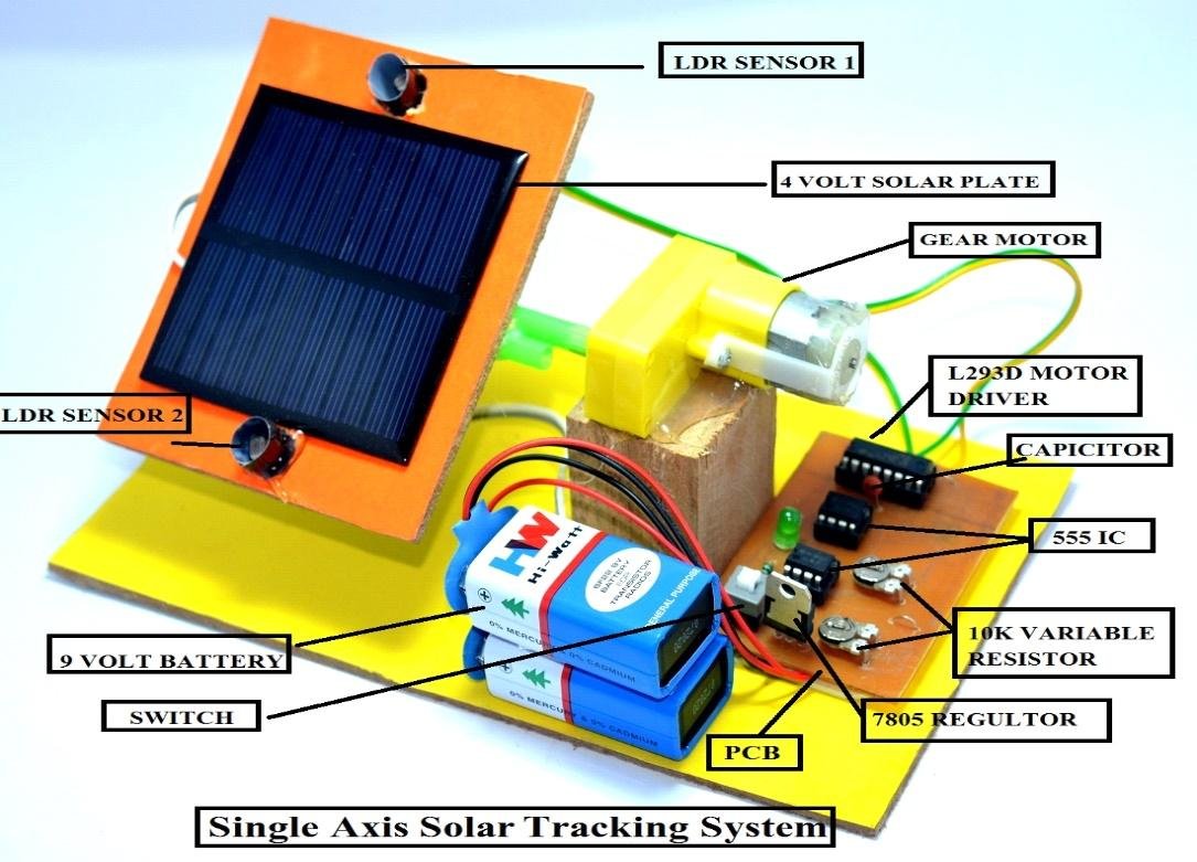
Step 1: Collecting the Components required for this project.
- LDR Sensors [2 Units]
- NE-555 Timer IC [2 Units]
- 10K Potentiometer [2 Units]
- 4 Volt Solar Plate
- VTR Switch
- 7805 Voltage Regulator IC
- L293D Motor Driver IC
- Gear Motor
- LED Light
- Capacitor
- 9 Volt Batteries [2 Units]
- Battery Caps [2 Units]
- PCB Board of the circuit
- Mounting Structure


Step 2: Assembling the Components – Circuit Design

Connect all the components with the required wires as shown in the above diagram.
__________________________________________________________________________
Thank you for learning with us. We hope all the steps and details are easy to understand. You can try to make your own Single Axis Solar Tracker by purchasing our kit for this project from the given link.
Video Demonstration Part 1
If you face any problem while making this project, please leave a comment down below.
For more Robotics projects join our SR Robotics community
![]() Get Latest updates from us on Telegram
Get Latest updates from us on Telegram
![]() To buy more kits, visit our website
To buy more kits, visit our website
![]() Subscribe us on YouTube
Subscribe us on YouTube
Viva Questions from SR Robotics:
- Which type of sensor is an LDR Sensor?
- Light intensity Sensor
- Proximity Sensor
- Tilt Sensor
- None of the above
Ans: Light intensity Sensor, LDR is known as Light Dependent Resistor. It’s value of resistance increases with the decrease in intensity of light. Here we used 2 LDR’s to compare intensities of sunlight.
- What is the use of 555 Timer IC?
- Astable Mode
- Monostable Mode
- Bi-stable Mode
- Inverter Mode
Ans: Inverter Mode, in this project we need to run the motor when solar panel is not receiving light which means when resistance is high in LDR we need to send a high voltage signal. But due to high resistance, LDR will send a low voltage signal. So, we need to invert the signal of LDR using 555 Timer IC.
- What is the output voltage of LM7805?
- 3.3 Volts
- 4 Volts
- 5 Volts
- 9 Volts
Ans: 5 Volts, the last 2 numbers of the voltage regulator IC represent the output voltage it supplies. For example: 7809 provides 9 Volts, 7812 provides 12 Volts, etc. Input voltage must be greater than or equal to the voltage value provided by the voltage regulator.
- What is the use of L293D Motor Driver IC?
- Converting the 5 Volts of circuit to 9 Volts for the motor
- Providing direction to the rotation of motor
- Switching Motor Clockwise, anticlockwise or stop directly on 9V supply using a low 5-volt signal from the circuit
- “b” and “c” both
Ans: “b” and “c” both, Motor Driver acts as a switch for motor which is directly connected to the 9 Volt supply. However, this switch is controlled by a low voltage signal provided by the LDR circuit depending on how much the motor needs to be rotated and in which direction.
- What is the use of a potentiometer?
- To change the resistance of the LDR
- To control the sensitivity of the LDR circuit
- To control the rotation of motor
- None of the above
Ans: To control the sensitivity of the LDR circuit, using this potentiometer we can control that at how much light intensity on LDR, the LDR circuit should send a HIGH voltage signal to the motor driver to turn the motor.
